Solutions
In order to select the best technologies and services, we have developed an information search process, active listening and constant training of our staff so as to be able to find the root cause of a possible decreased reliability or availability of the rotating equipment. Once the problem is detected, we design a solution application plan either during the comissioning, operation or scheduled stop/turnaround stages, with the sole objective of giving value to the production chain of our clients.
The main technologies and services we provide are:
Oil Mist Lubrication
Oil Mist Lubrication technology is used mainly to automate centrifugal pump lubrication, small steam turbines and cooling tower reducers in oil refining industries, petrochemicals and, on a smaller scale, in the iron and steel industry, Mining industry and power generation.
The main benefits achieved with this technology are:
- Increase in Average Time between failures. Depending on the starting point, it can double. Failures caused by lubrication problems in bearings and mechanical seals decrease sharply.
- Automation of lubrication tasks. Specially beneficial in dangerous plants such as Alkylation Units in Refineries. Presence time of lubrication operators on plant is reduced by more than 80%.
- Reduction in consumption of lubricants, cooling water and energy by optimizing the lubrication process.
- Positive impact on Security and Environment. Reduction in insurance premiums by reducing the risks of fire or accident in the plant.

Oil Mist Lubrication has revolutionized traditional lubrication and has gained more importance in industry since 1979, when the “Vortex” system was implemented. With this, the quality and reliability of the lubricating mist was enhanced and the monitoring systems and generating equipment controls were modernized. Installing a Mist Lubrication System results in more reliability and availability of process equipment, when comparing its tribologic performance to the traditional lubrication systems, as: the constant level of oil and grease. Oil Mist is a clean mixture of lubricant oil particles suspended in the air. It is conformed by one part of oil for 200,000 parts of air. The obtained particles are between 1 to 3 microns. There are over 100,000 machines lubricated by mist in the world in refineries, petrochemical plants and industry in general.
Mist lubrication as part of a new plant design
Many oil companies, engineering firms (EPC’s) and original equipment manufacturers (OEM’s) recommend oil mist lubrication as the design technology to lubricate centrifugal pumps in refineries and chemical plants. In API 610 norm, the pumps are designed to be lubricated by mist.
Mist lubrication as applied in existing plants
Mist lubrication can be applied without problems in existing plants with traditionally lubricated centrifugal pumps. The economic payback for such a project is typically 1 to 3 years. Quickest paybacks are typically in plants operating with hot fluids like coke, distillation, and crude or vacuum and catalytic processes. Mist Lubrication Systems can be open or closed looped – open meaning a one-time oil pass through while closed indicates constant oil recirculation. There are various mist generation consoles, according to the performance and requirements that best apply to the plant to be lubricated.
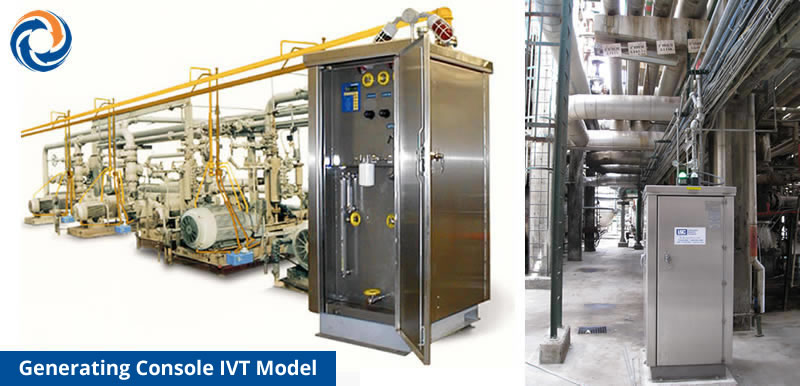
GENERATING CONSOLE IVT MODEL
Designed for systems with a large number of pumps (up to 80 aproximately) where maximum control and monitoring is required. Built-in microprocessor with DSC interconnection capacity. Up tp 933Bi ́s mist generation capacity. Available for explosive areas according to American classification ATEX and Inmetro.
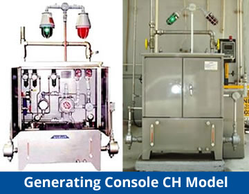
GENERATING CONSOLE MODEL CH
Designed for systems with few pumps (fewer than 15), with basic controls and monitoring. Dry contact alarm connection to control room. Available for explosive areas according to ATEX and Inmetro.
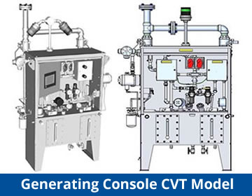
GENERATING CONSOLE MODEL CVT
cutting edge console with four different performance levels according to needs. The type of monitoring and control can be customized. Available for explosive areas according to American classification. In ATEX certification process.
GENERATING CONSOLE MODEL LUBRIMATE
Console to lubricate by mist one or two pumps simultaneously. Ideally designed for demonstrations, in factory, pumps trial and lubrication of isolated equipment.
STRAY MIST RECOVERING WITH DEMISTING
In the past, we installed recovery mist systems using Waste Mist Recovery Systems in several areas of the plant, each unit recovered stray mist from 6-10 pumps. That design required more air Supply points, and special procedures for mounting and installing the right scope in the piping. See fig 1.
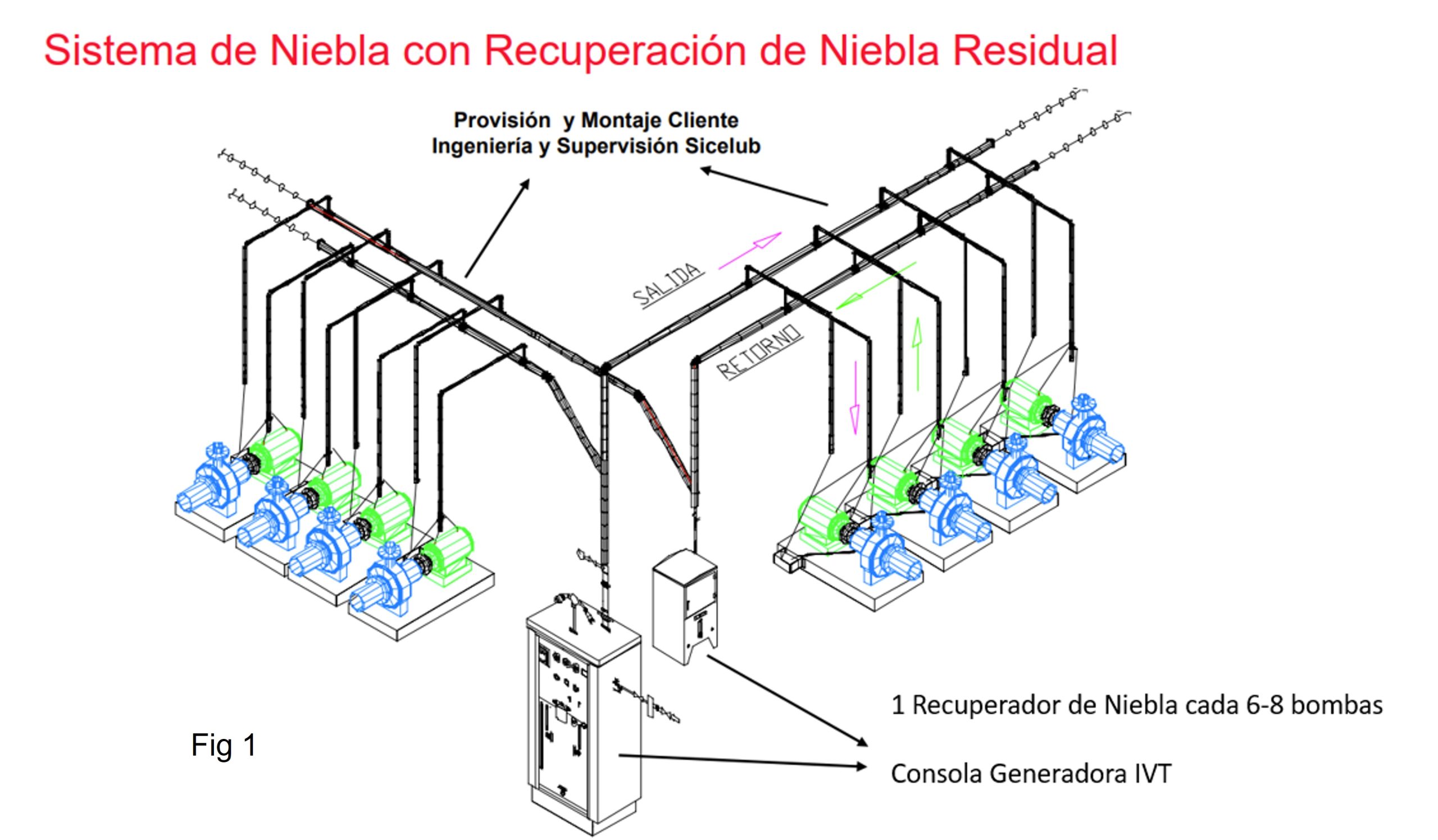
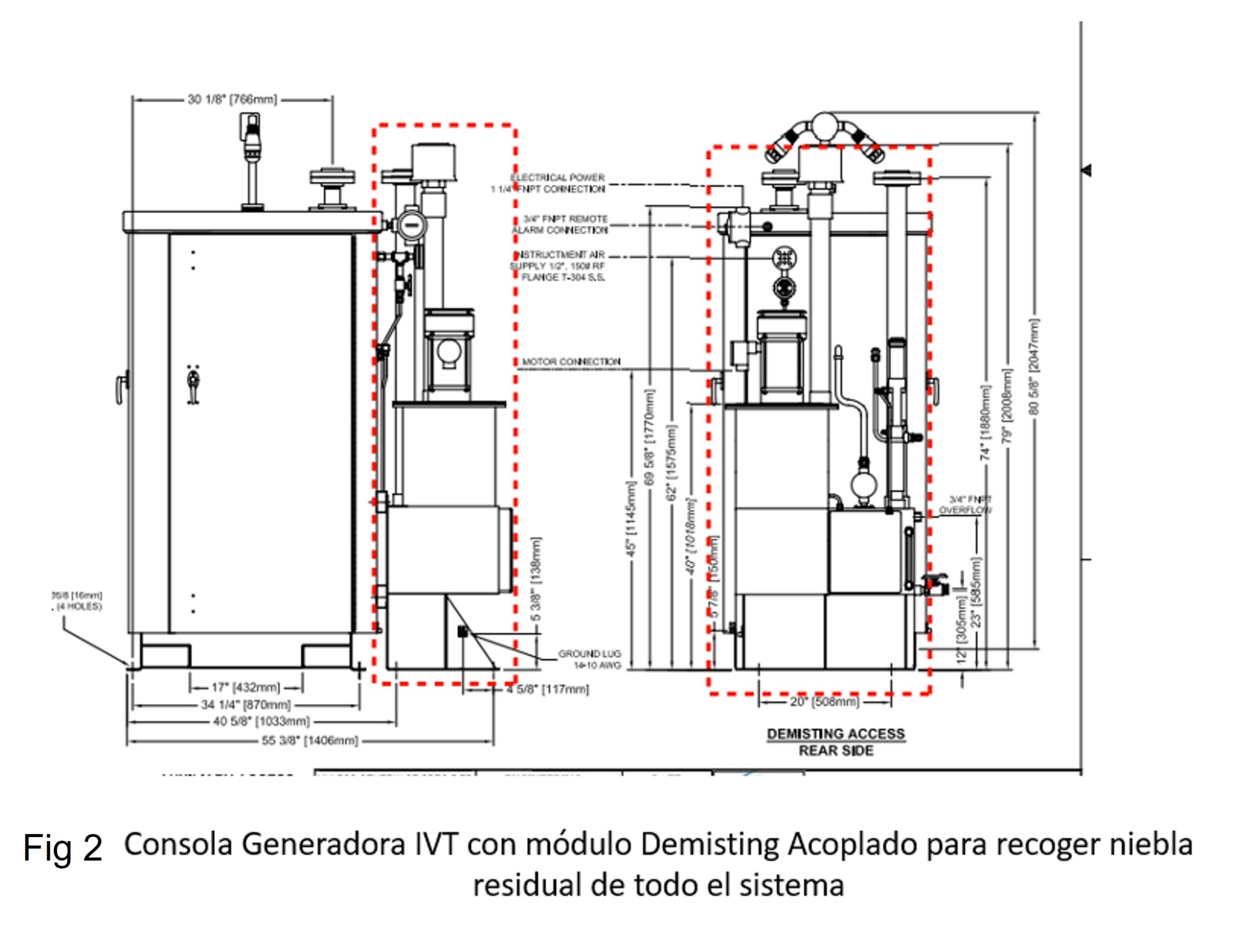
With this new design, we are installing a unique Demisting module, manufactured by LSC which is installed together with the oil mist generator. This module can recover stray mist from the whole system. We reduce installation time, air Supply points and basement. See fig 2.
Lubricant Purification – Thermojet Technology
There is no doubt that there is a direct relationship between the presence of contaminants in lubrication and hydraulic systems, with the Reliability and Availability of the lubricated Equipment. There are life extension tables that make it possible to determine the decrease in the probability of failure when the lubricant is kept free of contaminants such as water, particles, gases and varnishes. SEE GRAPH
Over time, different lubricant purification philosophies have been applied; from the original one, that connects a machine when a deviation is detected; Up to the present time, that considers autonomous purifiers of continuous operation to eliminate any pollutant that may be generated.
In the Sicelub Lubritech Group, there are different technologies to apply in each case; and according to the criticality of the rotating equipment.
PURIFIER EQUIPMENT THERMOJET
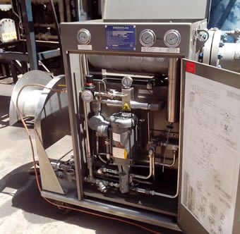 It is an autonomous unit that removes water, particles and gases from the lubricant. The system uses ambient air or injected nitrogen for impurity stripping, capitalizing on humidity stripping efficiencies linked to rising gas temperatures. As it can be seen in the animation (place youtube video of the Thermojet here); the fluid to be purified enters through a pump that sends it through a media filter where particles are removed. Then it goes into an electric heater, where the temperature rises to about 65 ° C. There, the fluid at high temperature and pressure is injected into a two-stage mixing chamber where vacuum driven gas injection occurs in the respective nozzles. The nozzles increase fluid speed, producing a drop in pressure that drives an influx of air or nitrogen into the lubricant. This mixture of oil, pollutants and air or nitrogen is deposited into a separation tank, at atmospheric pressure. The sudden pressure drop induces gas stripping by the evaporation of the fluid’s air or nitrogen, this stripping catalyzes mass transfer of impurities from the pure oil. Water in its three forms, plus light hydrocarbons, pass from the oil to the gas which is exhausted from the unit, leaving purified oil. The purified oil is returned to the customer’s lubrication system, through the purifier’s pump. This single pump is the system’s only rotating component providing high reliability through minimal moving parts.
The equipment has been designed to operate continuously, 24 × 7, in all environments including the explosive environments of Refineries and Platforms without the need for an operator; autonomously.
NEW MODELS OF THERMOJET OIL PURIFIER
Since 2022, Sicelub Lubritech Group launched to the Market, new Thermojet models, keeping the main characteristics of the equipment and adding new features. New available models are:
- High Operational Flow. Rapid model has two options for flow of 4 GPM (15,4 lts/min) and 11 GPM (41,5 lts/min) with additional options for operating at pressurized tanks, more filter elements, more heaters, etc.
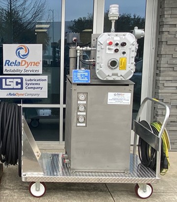
- Thermojet for non-explosive areas. This model is focused on markets like Power Gen, Pulp & Paper, and General Industry.
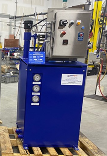
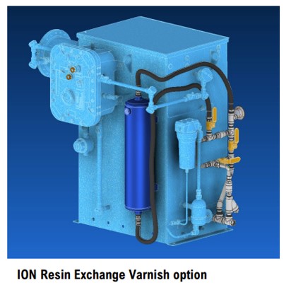
- Thermojet model for removing varnish. We have added a housing with ionic resins to the equipment which is able to retain varnish precursors (soluble). This is an ideal application for Centrifugal Compressors with Varnish, Gas Turbines in Power Gen or Hydraulic Systems. These models can be explosion proof or non-explosion proof.
In our meny for Webinars you can find more information about this equipment. https://sicelub.com/webinars/
VACUUM UNITS
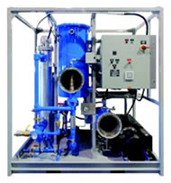 We have vacuum units to remove water in its three states and particles, with wide ranges of viscosity.
These machines can also remove wide ranges of flow rates and is suitable for classified and unclassified areas.
The design spirit of these units is to provide a service with a qualified and permanent operator and thus remove contaminants quickly, when it is required to act in Corrective Maintenance.
ISOPUR BALANCED LOAD AGGLOMERATION UNIT
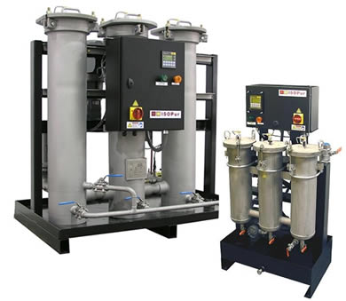 It is an autonomous unit that removes precursors of the formation of varnishes in oils. Applicable especially to gas turbines. As can be seen in the attached animation (place a youtube link), the fluid first enters a chamber with a pre-filter where particles larger than 10 microns are removed. In the second chamber, the circulation path is separated and a high voltage electrostatic field is applied, in such a way that the fluid that passes near the anode charges all the particles smaller than 1 micron with a negative charge; and the fluid that circulates near the cathode, charges them positive. In the end, joint circulation is favored; and there the phenomenon of agglomeration of opposite charges occurs; this means the millions of particles smaller than 1 micron become fewer particles; but now larger in size. In the third chamber, a conventional filter element is used to retain and remove all these agglomerated particles; so that oxidation precursors never form varnish deposits in the system.
This technology is recommended by gas turbine manufacturers, such as General Electric in their TIL 1528.
RETROFIT EHC SYSTEMS FOR BETTER CONTROL OF ACIDITY AND CONTAMINANTS
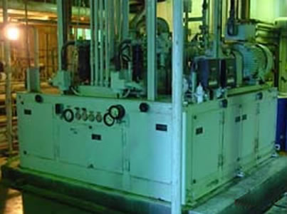
In EHC (Electrohydraulic Control) Systems of Steam Turbines, phosphate diester fluids are used for their better resistance to flame propagation, and thus avoid safety problems. These fluids are very sensitive to the presence of water and form acidic products with relative ease; therefore an external acidity treatment system is required. On the market there are Fuller soil / ground systems, activated Alumina, among others; that can improve acidity, but at the cost of introducing unwanted metals to the fluid.
The Sicelub Lubritech Group offers its Clients a Retrofit to place filter elements of Ionic Resins, flow regulators, filter elements for particles and special breather filters, which achieve the following benefits:
- More efficient control of acidity in the fluid.
- More efficient control in Cleanliness Code ISO 4406 or NAS 1638.
- More efficient control of moisture content.
This results in a longer life for the mechanical elements and the fluid.
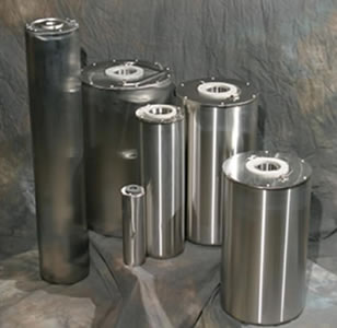
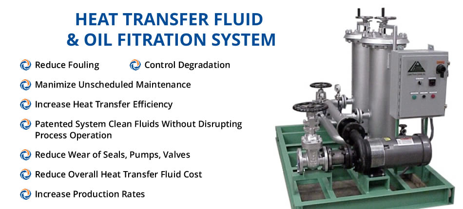
CONTINUOUS PURIFICATION EQUIPMENT OF THERMAL FLUIDS
There are several industries that use thermal heating systems; which means heating a mineral and synthetic fluid; which serves as a heat transfer medium. This heating accelerates the degradation of the fluid and undesirable contaminants and degradation products appear.
The Sicelub Lubritech Group has a wide range of external filtration and continuous purification equipment, to connect to Thermal Systems or Hot Oil System, and thus achieve permanent purification that extends the duration and properties of thermal fluids.
Filtration systems are custom designed, so if you want further information about them, you can fill out the following form. DOWNLOAD FORM
High Velocity Hydraulic Flushing – Turboclean
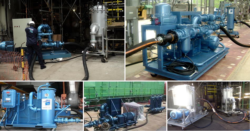
The objective of Flushing is to eliminate the contaminants present in the lubrication and control system, in an effective and fast way, before starting up a machine, in the Commissioning phase or after a Turnaround. That is, we are looking for Reliability in the start-up of the turbomachinery (stage with the highest risk of failure), and Availability, in other words, that the completion of this cleaning does not take more time than necessary.
There are different scopes of the Flushing service, to be selected according to the application:
High Velocity Hydraulic Flushing
The basic points recommended by the ASTM D-6439-05 Standard, for the Flushing to be successful,i.e. to remove the greatest amount of dirt from the system, and in the shortest possible time, include several aspects to be taken into account, being those that define a High Velocity Oil Hydraulic Flushing:
- – It must be done before the first start of the equipment (Commissioner), or in Scheduled Stops.
- – Achieve a turbulent circulation regime. Normally the Reynolds number should be greater than 10,000; to ensure that the different layers of fluid within the pipe have a better action on the inner walls of the pipe.
- – Use of high-efficiency filter elements. Filter elements with a βx factor greater than 1,000 must be used to ensure that the removed particles are removed from the system.
- – Use of Oil Analyzers on site. It is very important to have ISO 4406 Code (Particle Content) analysis equipment to monitor the procedure and determine when the cleaning has finished.
To increase the Re, you can choose to use external high-flow pumping equipment, use a lower viscosity fluid for the job, or heat it to decrease its viscosity. Generally, a combination of all the above options is chosen.
For example, to perform a Flushing in an 8 ”(203.2 mm) Pipe, using an ISO VG 32 Oil, and considering an operating temperature of 40 ° C, the minimum flow necessary to meet the minimum requirements of the norm would be about 1,230 lts / min. It should be noted that the pumps of the turbine lubrication system are generally designed to provide a Laminar Flow, therefore their use is not recommended for flushing. 
FLUSHING TO HYDRAULIC SYSTEMS WITH HIGH PRESSURE LOADS
For hydraulic systems with high length, even we need to reach a turbulent Flow, we need to reach high pressures, since conventional high velocity oil flushing skids aren’t the best equipment for this application. Sicelub Lubritech Group has incorporated to its fleet, equipment with more than 50 Bar of pressure. Typical applications are slide valves or Coke valves in Refineries or hydraulic systems in Shipyards.
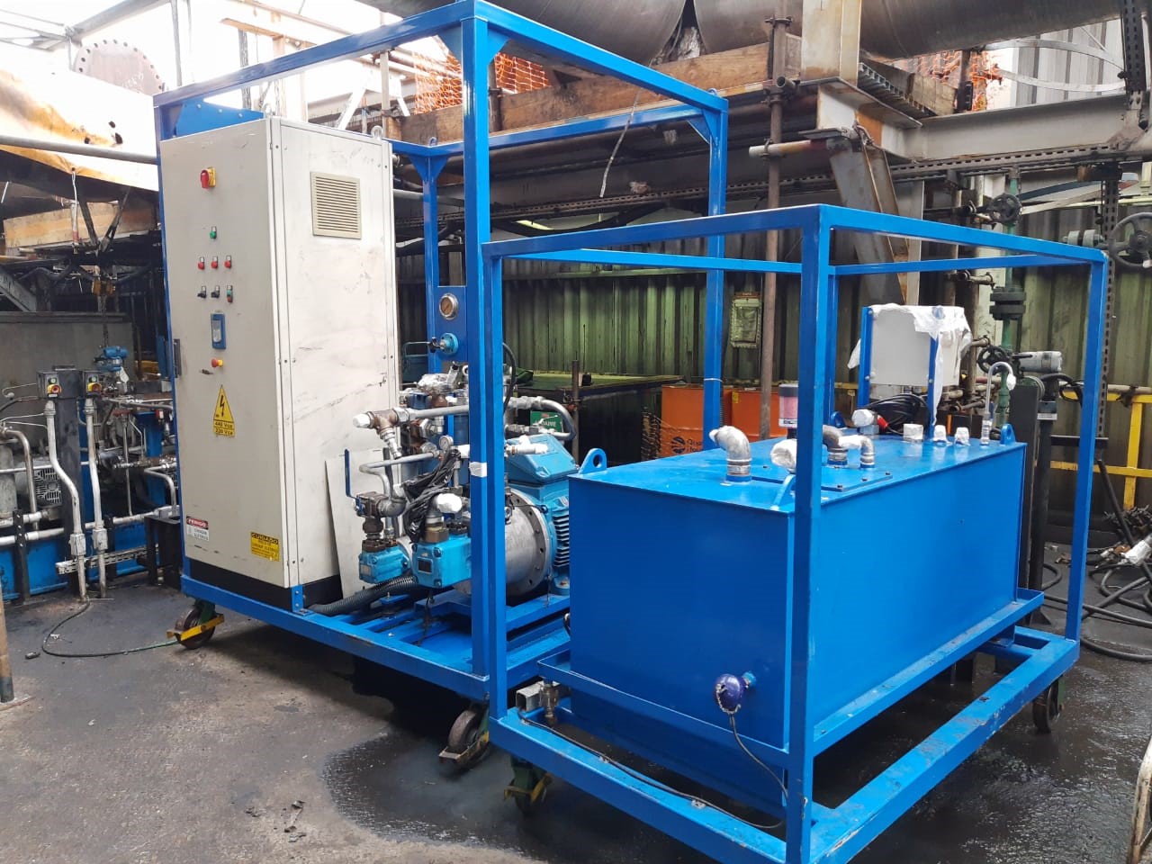 High pressure equipment for Flushing in hydraulic systems
FLUSHING TO MECHANICAL SEAL RESERVOIRS
During Commissioning stage, it is necessary to perform a Flushing to the reservoirs of mechanical seals. For this service, Sicelub Lubritech Group has invested in equipment designed for this application with different API plans. The equipment has to reach a turbulent flow, and perform on-line oil analysis.
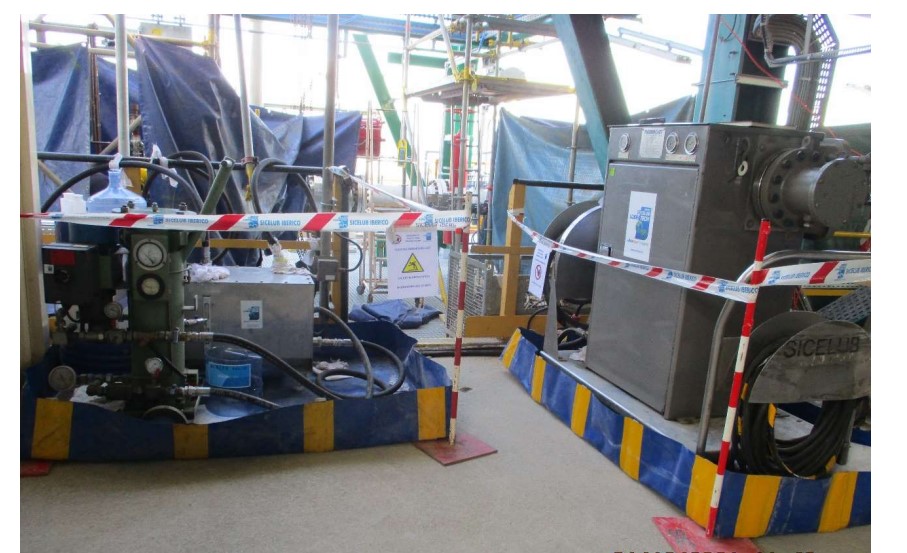
Flushing Skid with Thermojet Oil Purifier.
Flushing Skid with Thermojet Oil Purifier.
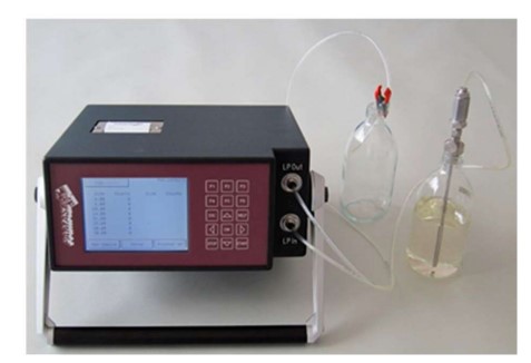
Electronical Particle Counter according to ISO 4406.
Electronical Particle Counter according to ISO 4406.
FLUSHING TO REMOVE VARNISHES:
In certain applications, the presence of varnishes in the system is evidenced during machine operation; so it is necessary to carry out a special intervention in Turnarounds, to remove these varnishes.
Some signs of the presence of varnishes during operation may be, clogging in servovalves of control systems, temperature increase in bearings, accelerated saturation of filter elements; and of course, high MPC values in the Varnish Potentiality Analysis, according to ASTM D-7843. Normally this problem occurs more frequently in gas turbines, machines in the Pulp & Paper industry; and centrifugal compressors operating at elevated temperatures.
The Sicelub Lubritech Group has developed a Flushing procedure to remove varnishes during Turnarounds to be applied in an alternative or complementary way together with the technologies of continuous lubricant purification to prevent and remove varnishes.
This Flushing procedure to remove varnishes consists of the addition of a chemical product specially developed by the Sicelub Lubritech Group to modify the solvency of the lubricant.
This product is added, after having stopped the equipment; but oil continues to circulate throughout the lubrication and control system; activating valves and controls, in such a way that the fluid comes into contact with all the internal parts of the system, and favors the detachment of these varnishes adhered to the system, taking them in solution with the fluid. After a period that can go from 8 to 72 hours; the mixture is drained with temperature, in such a way as to remove the varnishes from the system; leaving the system clean and ready for the operating oil charge. After performing a Flushing, the installation of equipment is recommended to prevent the formation of varnishes.

CHEMICAL CLEANING AND HIGH VELOCITY HYDRAULIC FLUSHING:
In some Industries, there are applications that require chemical cleaning, prior to a High velocity Oil Hydraulic Flushing. This is very common in new rolling mill lubrication systems in the Steel Industry or hydraulic systems in Oil Rigs.
The chemical cleaning procedure is varied and depends on the case; although for the most part it includes a previous degreasing step, then a chemical cleaning to carry out stripping, and finally a neutralization and passivation to protect the pipe, before starting with the High velocity Oleohydraulic Flushing process.
Sicelub Lubritech Group has the capability of performing a complete Chemical Cleaning and Flushing Service during Commissioning Projects, including process piping.

Equipment to perform Chemical Cleaning in Refinery under Construction.
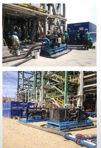
Disposición de Equipos para Limpieza Química en Refinería en Construcción.
Chemical Cleaning of Process Plant during Commissioning of new Refinery.
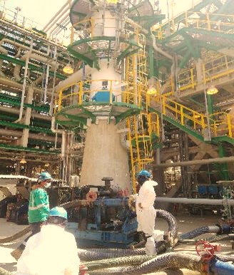
PADELI – Long Term Lubrication Services
PADELI PROGRAM is a modern business management practice that implements a cycle of continuous improvement made up of: Specialized activities, Engineering professionals specialized in Lubrication and applied integral Tribology. Normally, a preliminary audit is carried out to detect the areas for improvement that add more value to the installation and a program is designed according to those needs.
Benefits:
- – Increased Reliability of processes (MTBF).
- – Increased Uptime of the plant / useful life cycle.
- – Reduction in Catastrophic Failures of Critical Equipment.
- – Decrease in Unscheduled Stops.
- – Reduction of Maintenance Costs.
- – Reduction of the Consumption of Lubricants / materials.
- – Inventory reduction.
- – Increased security.
- – Professionalization of staff.
Advantages:
- – Focusing of the Client on the Main Business (CoreBusiness).
- – Mid and Long Term Strategic Planning. (3-6 years).
- – Sustainability in the Processes and Energy Saving.
- – Reengineering, Quality and Continuous Improvement.
- – Modernization and Automation of Processes.
- – Technological Transfer and Assimilation.
- – Multidisciplinary Participation in the Program (Teamwork).
- – Knowledge management.
- – Adherence to regulations and ecology.
Automation of Lubrication
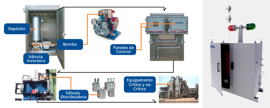
In process plants with a large number of lubrication points; either by grease or oil; There are opportunities for automation of lubrication and thus obtain benefits such as:
- – Continuous addition of lubricant in adequate quantities.
- – Improvement in the Safety of People by avoiding manual tasks in dangerous areas with difficult access or at height.
- – Increased reliability of the equipment, by having adequate lubrication.
- – Lower consumption of lubricants.
The principle of operation consists of using a pump to distribute grease or oil from a central reservoir to the necessary lubrication areas or points. This system provides the amounts of grease or oil specified by the manufacturers of machinery and components.
All lubrication points reached receive the optimal supply of lubricant, reducing wear.
As a consequence, the service life of the elements of the machine is considerably increased, greater efficiency is preserved in the system and in turn the consumption of lubricant is minimized
Storage and Application of Lubricating Oils in Plant
When a Tribological Audit is carried out, one of the important points to evaluate is the way in which the lubricant is stored. Typically, several opportunities for improvement are identified here; in terms of contamination control, unification of types and brands of lubricants, dosage and application before adding to the equipment, etc.
The Sicelub Lubritech Group has developed two solutions for this type of application:
LARGE LUBRICANT CONSUMPTIONS IN PROCESS PLANTS
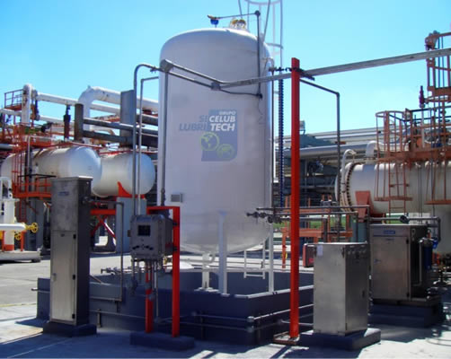
A typical application here would be a Refinery or Chemical Industry plant, where there are several turbochargers in relatively close areas. There are cases where 40-50% of the total lubricant consumption of a Refinery is in a relatively small area. In this case, we design, build and assemble a Lubricant Distribution System composed of tanks, pipes, filtration equipment, level sensors, pumps, etc; that automatically fills the equipment reservoirs. In this way we avoid moving drums or large cans and all the handling that causes potential accidents or contamination.
SMALL CONSUMPTION OF LUBRICANTS IN PROCESS PLANTS
Generally in each process plant, small amounts of various types of lubricants are used. In these cases, the Sicelub Lubritech Group designs, builds and installs Lubrication Stations (EDAs) provided with spaces to place drums, cans or tanks of each lubricant, with their corresponding breather filters and filling pumps with filters. All identified with color codes and with anti-spill security elements, etc.

The benefits of optimization in the storage and application of the lubricant are:
- – Personnel safety by avoiding handling of new and used lubricants. Positive impact of plant insurance premiums.
- – Elimination of movement and presence of full and used drums in Plant.
- – Increased reliability of equipment, by receiving clean, dry and cold lubricating oil.
- – Saving lubricants when buying in bulk.
- – Automation of lubrication. Elimination of errors of possible mixtures.
- – Environmental care.
- – Clean and safe work area for operators.
API 610/614 Forced Lubrication Systems – New and Reconfigurations
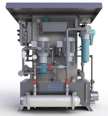
The Sicelub Lubritech Group has the possibility of providing Forced Lubrication Systems according to API 614 or API 610.
We can supply new systems, as well as reconfigure installed ones, providing them with greater reliability by replacing parts in poor condition and adapting them to current regulations.
We can also design the lubrication systems with their respective integrated purification equipment.
CONTACT US
If you want further information about our products or services, do not hesitate to contact us.

Argentina
Lubritech Argentina SRL
Calle 80 N° 175 entre 116 y 117
Villa Elvira – La Plata – CP1900 – Buenos Aires – Argentina
Tel: +54 0221 4571457 / 4212232 / 4539725
España
Sicelub Ibérico SL
Calle Bratislava 65
30353 – Cartagena – Murcia – España
Tel: (+34) 968 541 042
Cel: (+34) 618 730 333 (sólo temas comerciales).
Venezuela
Lubritech Venezuela
Brasil
Lubritech do Brasil
Alameda Plutão, 235
American Park Empresarial NR – Indaiatuba – São Paulo
Brasil – CEP 13347-656
Cel: + 55 (19) 3825-3669
Italia
Sicelub Italia
Colombia
Sicelub Colombia Ltda
México
Sistemas Centrales de Lubricación
Patriotismo 359
Ciudad de México – 03800 – México
Oficina: + (52) 55 5528 5014
Móvil: + (52) 55 3232 1991
Móvil: + (52) 55 3988 4202
Perú
Lubritech Perú
Av. Dionisio Derteano 184 Of. 603
San Isidro, Lima Perú.
Contacto: +51997519459 / +5492214854670.
Trinidad & Tobago
Lubritech Caribbean


